A long journey to somewhere
After a chance encounter with Anne of Green Gables and then a more serious encounter with metal in the sky driven by boxes with flashing lights that is Ken’s Prince Edward Island superstation, I became seduced with the idea that I could do that too, albeit on a super scaled down version. This has definitely been a case where the journey is as much enjoyment as the destination but I’m keen, very keen to get to that destination. Impatient, maybe but I’d like to use the fruits of my labor and move on to evolved projects.
I had always intended to have two Elecraft KRC2 band decoders, one per radio and with one under my belt and working, I realized I had left the other unbuilt kit many many miles away.
The purpose of the band decoder is to determine what antenna to request and assign to the radio. The 2×6 antenna controller has the smarts to handle contention when both radios request the same antenna and ensure neither radio erupts into smoke.
The full complement of phase 1 of my station automation targeted at Suitcase DXPeditions are;
- SO2R controller to mange audio between the two radios and which gets to transmit when I say “howdy doody” on the air
- 2×6 antenna switch parcels out up to 6 antennas between my two radios
- KRC2 band decoder (one per radio) instructs the 2×6 which antenna the radio would like


Not wishing to buy another unbuilt Elecraft KRC2, I decide to pull forward some of my plans and create a bespoke 2×6 antenna switch controller. Seems easy enough but that is the curse of an optimist which I eternally am.
The requirements are straight forward;
- Interpret N1MM’s antenna selection messages (sent via USB or UDP)
- Assert 12v on a line to the 2×6 antenna switch
Neat and tidy does it
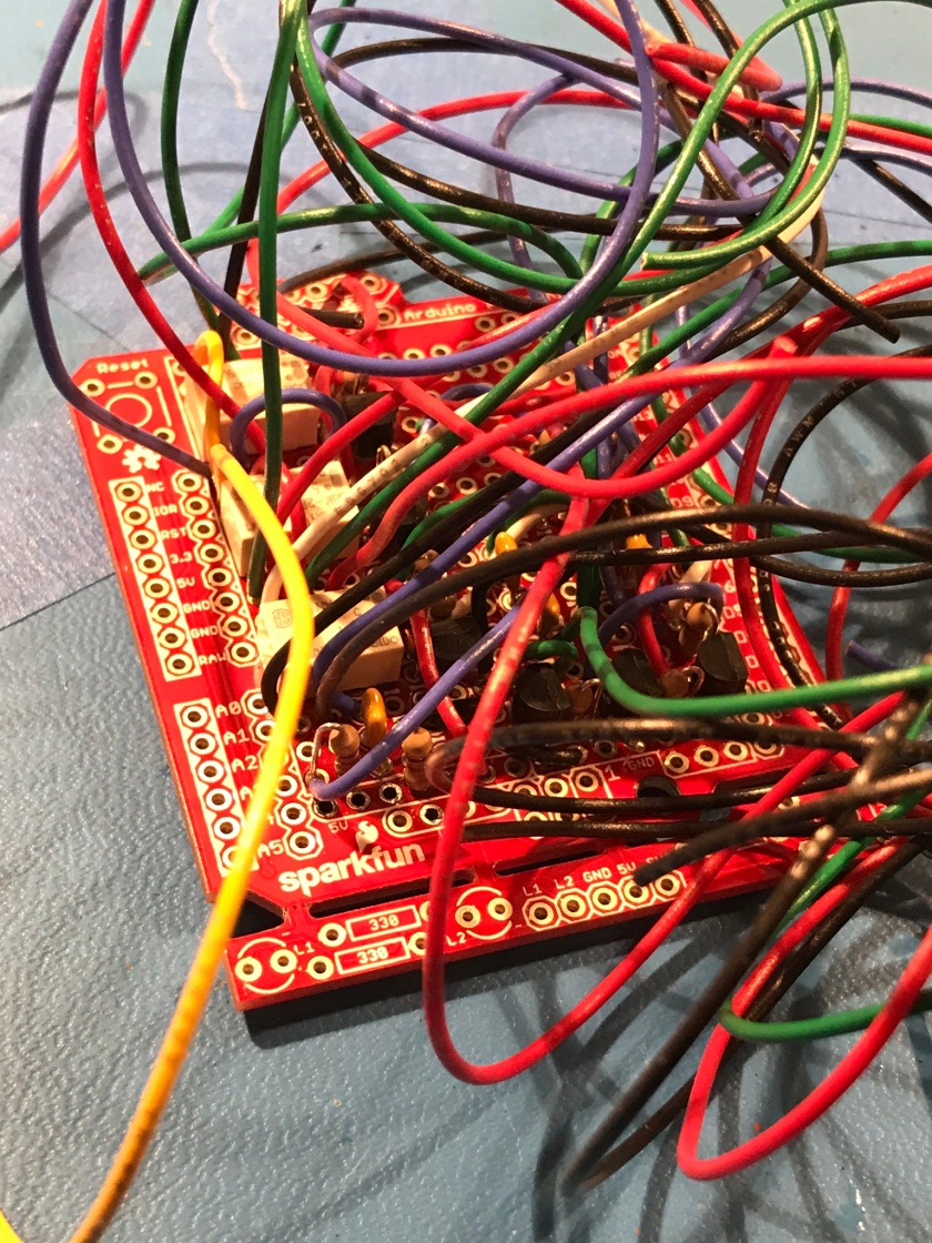
To my chagrin, I realized when building the SO2R controller that I had been woefully optimistic around miniaturization to the point I had a tough time telling what when to where. I love to iterate and improve and I was determined that my bespoke solution be cleaner, neater and more reusable than the SO2R controller which despite wires galore does actually work (I’m also tenacious and don’t like failure).
A detour to nowhere
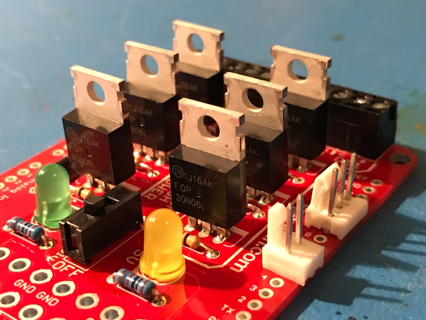
I’m not sure how I found it but buried deep in SparkFun’s website is what seemed like a godsend. A small board that could be Arduino controlled and under its command could assert 12v (or 5v) on multiple outputs. Parts sourced, a circuit board and life looks good and a chance to avoid the rat’s nest.
Buy, build and I’m off to the races.
In hindsight the description is a little ambiguous and with my EE naivety I didn’t think to ask the all important question of how the 12v positive voltage is asserted. Turns out two schemes exist; one where 12v positive is always present and the return path is switched to ground or the 12v positive line is low and then switched high resulting in 12v. I knew I wanted the later but this little SparkFun wasn’t much fun as it performs per the former description and each and every line is 12v high, in essence having each radio requesting every antenna simultaneously.
Absolutely not what I want.
Failure.
Drats!
The money isn’t the issue but more the frustration and time. On the positive side (pun intended) I’ve learnt a lot and truth is I’m sure I’ll use this circuitry somehow and somewhere, just not her.
Fortune Drive to the rescue!!
I’m staring at the data sheet. It seems really appropriate at this point to fully understand how this little chip works. I’ve read it, I think I’ve got it but the address, 2180 Fortune Drive, San Jose seems so so familiar to me. Why is this address so familiar and I can’t shake it loose. A little Internet sleuthing and low and behold I’ve worked in that building for almost five years when it was Novell’s and I was Novell’s. Go figure that probability.
Micrel, the new inhabitants make many chips but mine is the MIC 5891. Truth is this is used in the KRC2 and another joy of this journey is pouring over other people’s master work and seeing how things are done especially for this neophyte EE. What’s that saying, “imitation is the best form of flattery….”
Prototype that baby
Not wishing to be disappointed after melting solder, I decided to breadboard the solution and whip up a little test software to assert 12v to each of the antenna switch lines. Along the way I tried to see if the 5v output from an Ardono (i.e bypass the chip entirely) would suffice but alas not.
I’m now committed to the MIC5891.

We’ve got a winner
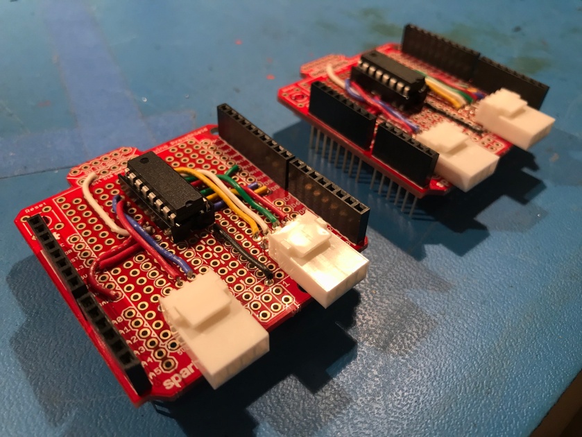
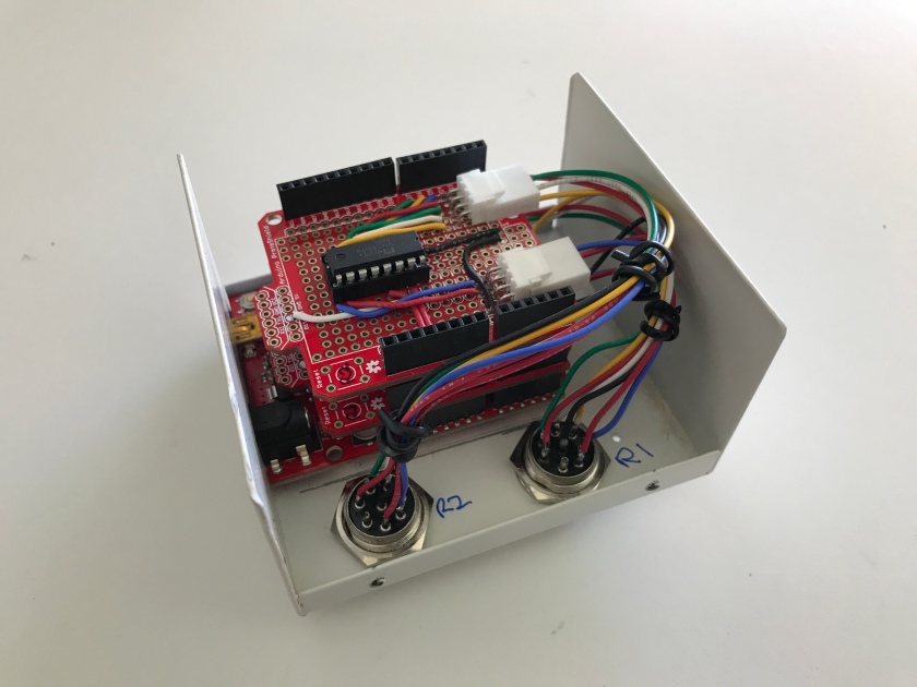
Proof of the pudding is in the eating and I’m happy and put effort into creating two boards (one per radio) with a special emphasis on “Neat and Tidy” and “Reusability”. The later being achieved by having the board fully separate through pins and plugs from the rest of the solution.
…and a little bit of software to complete the solution
The Elecraft KRC2 band decoder is a lot more versatile than this solution and would achieve my specific goal of requesting an antenna at the 2×6 switch my monitoring radio to computer rig control messages. The upside is radio initiated band changes and hence antenna requests are also interpreted and actioned. My solution doesn’t do that. It’s tailored very much to N1MM (my preferred contest software) and is seen by N1MM as a special external USB connected controller/device that speaks the OTRSP protocol. Very specifically and within my solution I parse and action the AUX commands of the following format;
- AUX100 – radio 1 requesting antenna 1
- AUX200 – radio 2 requesting antenna 1
- AUX101 – radio 1 requesting antenna 2
- etc
It’s very feasible to daisy chain two or more MIC5891 but I chose to devote 4 Arduino digital pins to each MIC5891 board for a total of 8 digital pins being used.
#define R1_MIC_OUTPUT_ENABLE 11
#define R1_MIC_STROBE 12
#define R1_MIC_CLOCK 9
#define R1_MIC_DATA 8
#define R2_MIC_OUTPUT_ENABLE 10
#define R2_MIC_STROBE 7
#define R2_MIC_CLOCK 5
#define R2_MIC_DATA 6

Enclosures terrify me
Not the ones that you might park your sheep in nor the ones that we step into and call home but rather the ones I grind and craft in my maker lab that is also my garage.
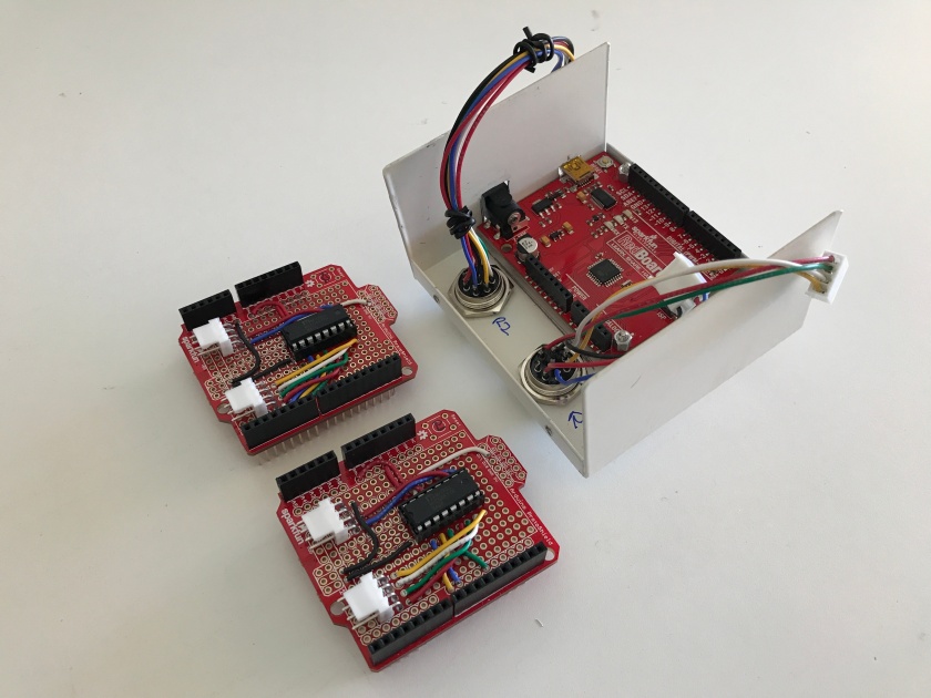
Determined to do better and also be more self sufficient, I took the teaching that Scott (AK6Q) imparted and crafted an opening for 12v and the RedBoard USB connector. Worked out well enough especially after using a debarring tool and files per Scott’s lesson.
I used a vice and a step drill bit to make some pretty descent opening in the case and mounted two 8 pin connectors to ferret the 12v signals to the 2×6 switch.
All in all I’m happy with the enclosure grinding, boring and shaping work.
I’ve been staring at the Hammond enclosure for a while. Its rather nice and pretty hefty. I’ve drawn paper templates but I haven’t really connected the dots to see how I place the template correctly on the lid. There’s a lot of holes that have to be drilled in pretty much the right spot relative to others. Looks tricky, days go by and I realize I’m not there yet.

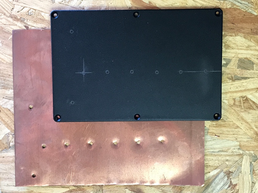
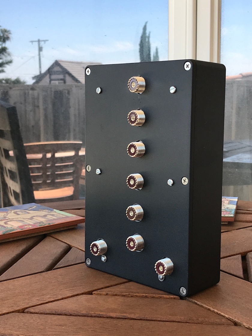
Mark is a master craftsman and a friend. I casually wander by to see if he’s willing to help out with what I’m sure is a quick job. He’s game and after a few trial runs making templates to match the center holes, the lid is being ground out and hey presto we have a really good fit and I’m ecstatic.
Thanks Mark.
What’s next?
- First thing is to use this little trio of boxes.
- UDP, a better way. Larry K8UT one the N1MM developers suggested via a web watering hole that I try using the UDP carriage approach that is an enhancement to N1MM and a modern day alternative to USB connecting off board boxes to a PC. It uses an XML message format that is disseminated in UDP packets over a network to listening devices. Very much on my list and I have some ideas how to do this using a Raspberry Pi.
- Rubicon based wilderness contest station. I like to reuse my solutions and while this is absolutely intended for portable suitcase type operations in wherever, I also have a desire to operate from my Jeep Rubicon Hardrock that has taken me to some outstanding remote location for something like the Cal QSO party, ARRL field day or the 7P QSO party. To that end I’ve been prototyping a solution using 67Design parts (there are awesome) and Scott’s (AK6Q) help as he is also Jeep guy and probably more so than me.


Paul great work and tenacity there! Glad to see a plan coming together! I can’t wait to see it in action in the Jeep!
73 Scott AK6Q
LikeLike
Beatiful designs! 73 de Bjorn SM7IUN
LikeLike