
Imagine you are listening to a music FM station, tire of it and twiddle the big knob on the radio until you find a station more to your liking. What you are doing is tuning the radio to the frequency of the station to hear it. A sub circuit that enables the tuning is called a Variable Frequency Oscillator (VFO) and radios have many sub circuits including audio amplifiers, frequency displays etc. Not to get to much into the wonder of resonant circuits, its established that a collection of parts (transistors, resistors, inductors, capacitors….you know all that old school analog stuff) can be connected up to create frequencies in different ranges. In my FM radio example the frequency range is roughly 88-108 Mhz.
The Intermediate ham license assessment includes using a VFO and optionally offers it up as a construction project. The later is what I did first and have documented here and very specifically a VFO roughly in the range 3.5-4.0 Mhz (far away from the FM examples above) which covers a ham radio band around 80 meters (80m).
The RSGB points out that the circuit included in the study book can be touchy to get working and some of the parts are harder to get than not and therefore an alternative circuit is offered which is what I elected to build.

If you buy an electronic kit you will get all the parts needed including a nice professional looking circuit board that you stuff with the supplied parts. Fun to do and minimizes the chance of messing up and my recent Elecraft 100 Tuner is a fabulous example.
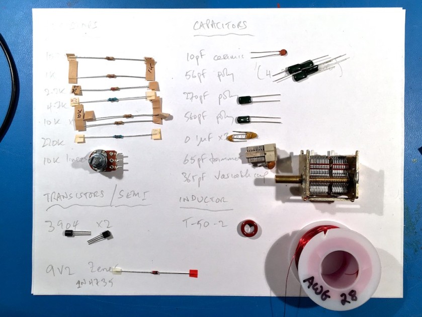
In this case no kit was readily available and so the first step is to rummage around my “junk box” and see if I can find the needed parts.
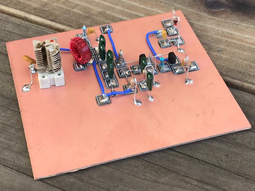
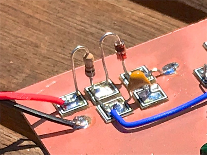
Various styles of ad hoc construction exist from dead bug, breadboard, vero board through to Manhattan style. I prefer the later as its easier to follow and I like neat things!
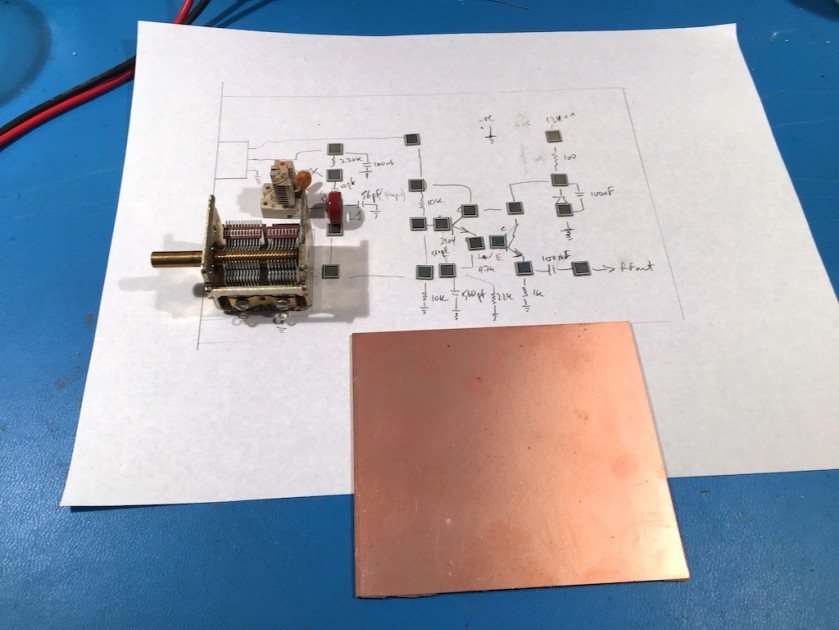
Having confirmed I have the parts, my next step is to map the circuit through a couple of iterations to something that is MeSquare placement on a copper board.
I heard/read a statistic that something like 50% of home-brew circuits never work and end up in a pile somewhere in the shack. I’ve had my share of failures and they are really frustrating for obvious reasons. What I have learnt is to be patient, methodical and check things before and during the build process. I check the integrity of solder joint visually and sometimes with a continuity meter, takes a few seconds and can avoid that painful frustration. With this in mind I’ve tried to invest in a few basic test/diagnostic tool especially given the diversity of component sources; some reputable, some suspect, some criminal and some a happy surprise. So much is available on eBay and the web at really attractive prices that are hard to resist and so the test/diagnostic gear can take to mystery our of what I have acquired.

Pad placement on the copper board requires a little thought. Too close and your components look like a lonely island on a sea of copper. Too spaced out and you run out of copper board and your’e somewhat up a creek without a paddle.

Part of the attraction to this circuit was RSGB’s claim that it was forgiving of transistor specs. My two triffid black transistors are the ubiquitous 3904, a very fine and universal NPN device.
I didn’t have the super narrow enabled wire that the RSGB circuit called for and struggled to get the full 60 turns wrapped around the donut toroid core ending up with only 55. 10% off seemed fine in the grand scheme of things and my proffered but toxic (hence have a fan running and use a face mask) approach has me removing the enamel with hot solder.


Did it work first time?
Unfortunately not despite my great efforts to check component values, double check solder joints. Its usually at this point I would curse in frustration but the upside to all the pre and during build checking is you narrow down what the issue category is. Beyond dry joints, missing or incorrectly placed component are leading suspects. Most of what I have used are bi-directional and doesn’t matter which way they are installed. A few things do and I quickly realized my Zener diode was installed the wrong way.
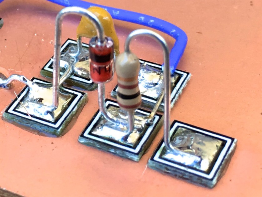
Zener corrected and it works.
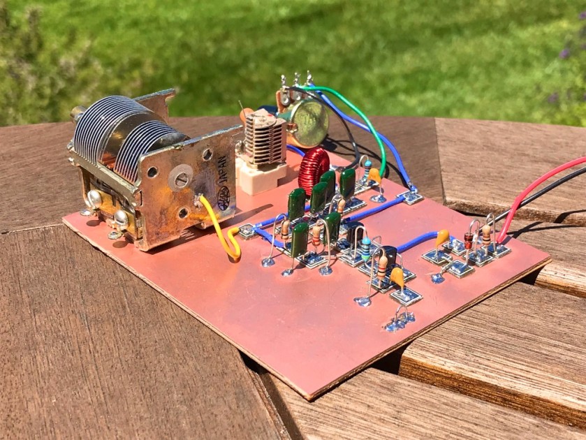
A nice 3.8Mhz signal is being generated. After a bit of calibrating the VFO puts out a frequency in the range 3.6 – 4.0 MHz (the SSB portion of the 80m band). Excellent.
Here are couple of videos and my new VFO working.
Edinburgh here I Come!!

Hey – that Manhattan construction looks fantastic Paul! Were you using round-nosed pliers to get those beautifully curved component leads? Kudos to the British authorities for having a building requirement for at least part of their licensing process.
Nice work!
Dave
AA7EE
LikeLike
Thanks Dave, I bend the resistor etc leads either around a small screw driver shaft or via a pair of pliers as you indicated.
Fortunately the TSA where not unduely alarmed at the project in my checked bag and it’s in the UK now.
I’m very supportive of the assessment steps that prospective licensees go through in the UK. Definitely more work for candidate and examiner but the end result is a ham that hits the ground running.
Paul
LikeLike
What a nice project …. when searching on YouTube your videos never showed up in the results. Luckily I found the article. You have no idea for how long I’ve been searching for a simple VFO as this one. I saved it so I can read properly later on today and start getting parts from my own junk box hehehe. Thank you for sharing this. 73
LikeLike